Description
Our project is to create a Computer Vision algorithm and setup to pilot a remote-controlled Arduino robot. Using a top-down viewing camera, we will use Computer Vision to analyze lines drawn that will be converted into directions for the robot to follow. What’s interesting about this project is that it employs Computer Vision and image analysis to analyze hand-drawn paths and use that to control a robot. The main challenge this presents is the use of computer vision to process real-time changes in the drawings and turn that into directions for the robot to understand. This project relies on line detection in Computer Vision and the use of common sensors in robotics such as an ultrasonic sensor and a Raspberry Pi camera.
Prior Work in the field
Our first reference is the Aruco Tag Guided Drawing Robot. This project has similar attributes to ours, including controlling a small Arduino robot using hand-drawn commands and using Raspberry Pis for communication. Although similar in nature, this project does have a few key differences such as the use of a touchscreen for the drawn instructions, whereas we plan to use a pen and paper with Computer Vision to process the drawings. Our implementations of Computer Vision will also be different, as they are using April Tags with CV to identify where the robot is on a grid, and we will be using line detection and other methods to analyze the drawings.
System Architecture
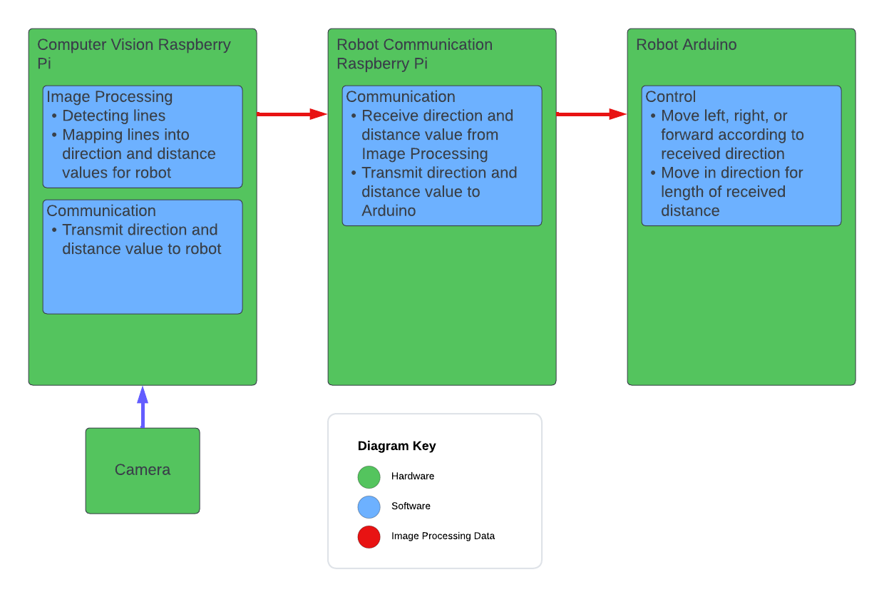
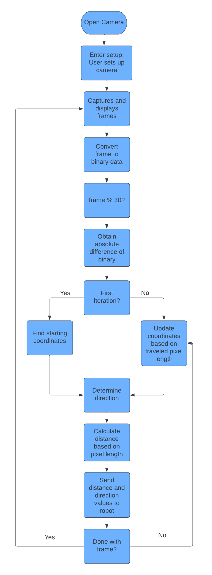
Methods
In our project, we used multiple Computer Vision techniques to analyze the hand-drawn paths. Below is an image of our CV algorithm for converting the hand-drawn lines into a direction and distance for the robot. One of the major techniques we use is to convert a video frame into a binary image where the back lines are defined as 1, and everything else is defined as a zero. This results in a difference image that we can analyze with only the drawn lines. Once we have this difference image, we use another technique to find the length and direction of the line by using the starting and end coordinates of the line to determine direction, then using the pixel count of the line to determine distance.
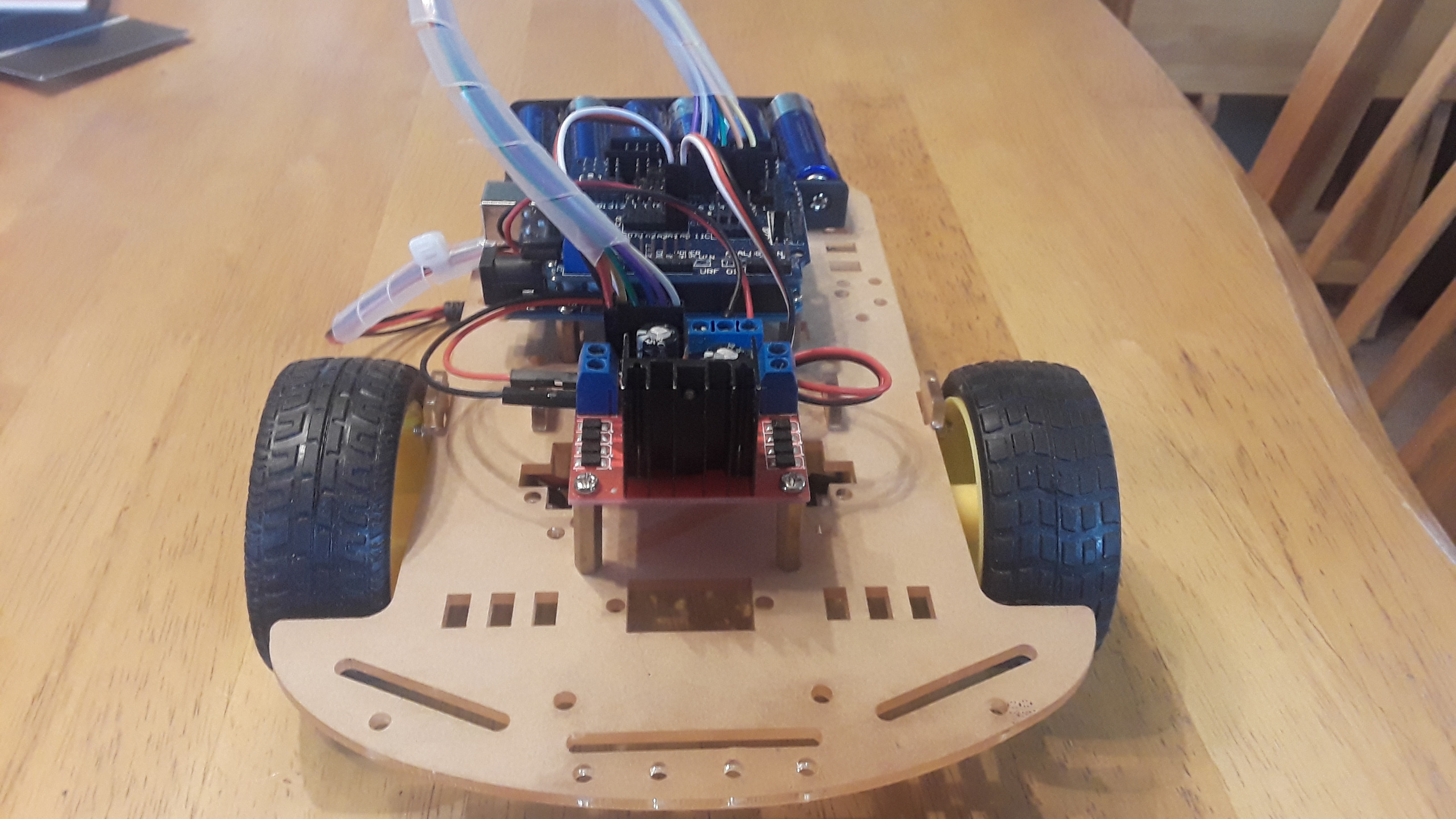
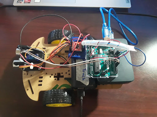
HARDWARE
THE hardware for this project builds upon my pre-existing work developing the Michigan Engineering Zone Kitbot. It uses the same chassis and motors and was initially planned to use the same motor driver, although we converted to the Sparkfun redbot motor driver for less power consumption. This robot uses a raspberry pi 4 for wireless communication and controlling the Arduino Uno that controls the Robot's Drivetrain. The Arduino has a script on it to receive a direction command and a distance value from the Raspberry Pi and then sends voltage to the motors to move accordingly.